Next,
the ACR floor is glued to the bottom of the alternative
floor, (the one with the handrail fitted to it). We have
to centre this one by eye.
|
|
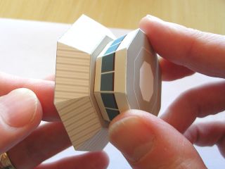
This is what the completed ACR assembly looks like when turned
the right way up. |
| |
|
|
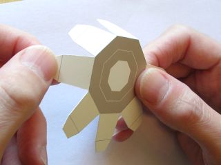
We fold down the sides and tabs on the Visual Control Room
(VCR) frame. |
|
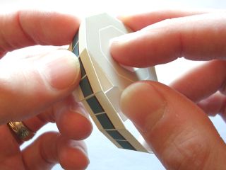
Then glue the VCR walls around the frame one section at a
time. These need to be fitted so that the frame closes together
to form the correct tapered shape. |
| |
|
|
When the VCR walls have all been glued in place, there is
still a gap between the end walls. This is closed with the
wall joiner, carefully inserted using tweezers. |
|
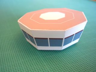
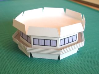
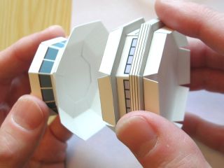
The finished VCR looks like this. |
| |
|
|
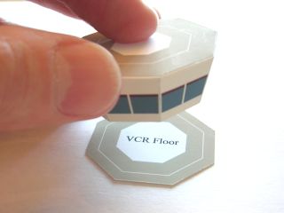
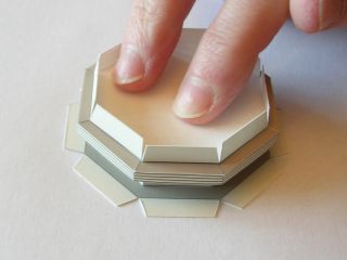
The VCR
is glued to the floor, making sure it is centred. This needs
to be pushed down gently until the glue is dry.
|
|
The ends of the top cone are glued together, as we did with
the other cone shapes. |
| |
|
|
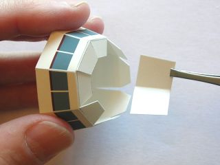
Glue is applied to the tabs on the top cone, and the VCR floor
is fitted to it, again making sure it's nicely centred. We
can push against the tabs from underneath, to make sure that
the VCR is stuck in place. |
|
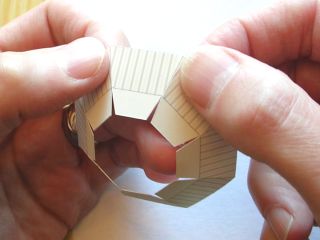
Then we put glue on the tabs around the ceiling of the ACR
and fit this inside the top cone. It's a good idea to put
quite a bit of glue on the tabs in situations like this, to
be sure they will stick, as we can't directly press them into
place. |
| |
|
|
| <
Page 3 |
|
|

